
اترك رسالة
إذا كنت مهتمًا بمنتجاتنا وتريد معرفة المزيد من التفاصيل، فيرجى ترك رسالة هنا، وسنقوم بالرد عليك في أقرب وقت ممكن.
A ground mount solar array is only as stable as what holds it in the soil. Modules, rails and clamps get the attention, but the foundation absorbs every wind uplift, snow load and frost movement the site will see for the next 25 years. Choosing the right foundation — and installing it to a verified capacity rather than to a habit — is the difference between a ground mounting system that stays plumb and one that needs re-levelling, re-torquing or pile replacement within a decade. This guide covers the five foundation types used on modern ground mount projects, how each one is actually built, which ground conditions suit it, and the advantages it brings to the array.
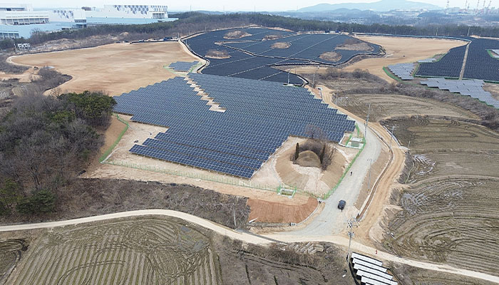
Foundations are usually 8–15% of a ground mount project budget, yet they control the structural behaviour of everything above them. The design is driven by six inputs: soil bearing capacity, frost depth, groundwater level, wind uplift at the array edge, seismic load, and the dead load of the modules plus snow. Change any one of them and the correct foundation can change with it. That is why a foundation detail copied from a neighbouring project is one of the most common — and most expensive — mistakes in ground solar construction.
A foundation has to do two jobs at once. It must carry the array downward without settling unevenly, and it must resist the upward pull that wind creates under the modules. A foundation sized only for compression will pass inspection on a calm day and fail in the first storm. Every type below is judged on both capacities.
A ground screw is a hot-dip galvanized steel shaft with one or more helical flights at the tip. A hydraulic driver rotates it into the soil at a controlled rate until the design depth and torque are reached, then a pile cap or post adapter is bolted on. There is no excavation, no concrete and no curing time, so racking can follow the same day.
Best ground conditions: firm loam, sand-gravel, farmland, grassland and sites where spoil or heavy machinery access is restricted. Advantages: one crew can install well over a hundred screws a day, the torque log documents capacity pile by pile, the foundation is removable and relocatable, and there is no concrete carbon or wash-out risk. Limits: boulders and shallow ledge cause refusal, and very soft peat or organic fill may need a larger helix, a deeper shaft or a different foundation altogether.
Driven piles are H-sections or C-sections hammered into the ground with an impact or vibratory driver until they reach design embedment or refusal. The top of the pile is cut to elevation, and precast or bolted pile caps carry the purlins and rails. On large arrays, some rows are deliberately battered at an angle to resist uplift more efficiently.
Best ground conditions: flat, well-drained sites with competent granular soil, and cold climates where the pile can be driven below frost depth. Advantages: the lowest foundation cost per megawatt at utility scale, very high uplift capacity, no concrete and no curing, and a driving log that records penetration and set for every pile. Limits: noise and vibration, obstruction risk in filled ground, and rock that requires pre-drilling before driving.
A concrete pier is an augered hole, typically taken below frost depth, fitted with a rebar cage and anchor bolts or an embedded base plate. A setting template holds the anchors at the correct spacing and elevation while the concrete is poured, and the pier is left to cure before racking is installed. On rock, the pier can be replaced by a rock anchor or a short drilled-and-grouted socket.
Best ground conditions: expansive clay, soft or variable fill, high wind and heavy snow zones, tracker foundations and any site where driving is impossible. Advantages: the highest compression and uplift capacity of any option, predictable behaviour in almost any soil, precise finished elevation, and a service life that comfortably matches the module warranty. Limits: the slowest option, weather-sensitive during pouring and curing, dependent on concrete logistics, and effectively permanent.
Ballasted foundations hold the array down with weight instead of embedment. The subgrade is graded and compacted, precast blocks are placed in a designed pattern, and the racking is anchored to the blocks. The ballast mass is calculated against the uplift at the most exposed corner of the array, not against the average.
Best ground conditions: landfill caps, brownfield and contaminated land, high water table, leased sites that must be restored, and any location where digging or penetration is prohibited. Advantages: zero ground disturbance, fully removable at end of lease, rapid installation with no curing, and no risk of hitting buried services. Limits: heavy transport and lifting, the subgrade must carry the block load without settling, high-wind sites need substantially more ballast, and the footprint grows because blocks cannot share space with racking posts.
A helical pile takes the ground screw idea to structural scale. A steel shaft with one or more helixes is torqued to a specified capacity, cut to elevation, and finished with a concrete cap or a steel bracket that receives the post. Because load is transferred well below the active soil zone, it works where shallow foundations move with the seasons.
Best ground conditions: expansive clay, frost-heave regions, high groundwater, soft surface layers over competent strata, and retrofits where minimal spoil matters. Advantages: high capacity in both compression and tension, small installation equipment, verifiable torque, and very little excavated material. Limits: higher unit cost than a simple ground screw, and rock or dense cobbles can stop installation.
Start with a geotechnical report, not with a preferred product. The report should give bearing capacity, soil classification to the expected embedment depth, groundwater level, frost depth and any obstructions. With those numbers, the choice usually narrows quickly.
Sand and gravel: driven piles for large arrays, ground screws for small and medium projects. Both rely on friction and end bearing and install quickly. Clay and expansive soil: cast-in-place piers or helical piles taken below the active zone, because seasonal swelling will lift a shallow foundation. Rock: rock anchors, drilled sockets or cast-in-place piers; driving and screwing will simply refuse. Landfill, brownfield and contaminated land: ballast, since penetration is usually barred and the cap must stay intact. High water table: helical piles or ballast, with corrosion protection specified for the wet zone. Frost regions: every type must reach below the frost line, which often makes driven piles the economical choice. Slopes: stepped post lengths and deeper embedment on the downhill side, with row-by-row structural review above roughly 20% grade.
For utility-scale arrays on competent soil, driven piles are normally the lowest cost per megawatt. For small and medium projects, ground screws often win because there is no concrete, no curing and no heavy civil equipment on site.
Not reliably. Boulders and shallow bedrock stop the helix and can damage the shaft. Rocky sites are better served by rock anchors, drilled sockets or cast-in-place piers.
No. Ground screws, driven piles and helical piles are all concrete-free. Concrete is only required where the loads, soil or site restrictions make piers or ballast the correct choice.
Depth follows the geotechnical report and the local frost line, typically in the range of 1.2 to 2.5 m for commercial arrays. Capacity, not depth, is the acceptance criterion — which is why torque readings, driving logs and pull tests matter.
9Sunsolar engineers ground mounting systems around the foundation the site actually needs — ground screw, driven pile, concrete pier, ballast or helical pile — with hot-dip galvanized steel, matching clamps and a bill of materials that fits your soil report and wind load. Send us your layout, geotechnical data and module type, and our team will return a foundation and racking proposal for your next ground mount project.
اشترك في النشرة الإخبارية لدينا للحصول على معلومات التحديث والترويج والبصيرة.


 دعم شبكة IPv6